News
Minelab GEOSENSE-PI The Next Level
Minelab GEOSENSE-PI
First of all I hope everyone had a great Christmas and a safe New Year. I have actually just had my first set back for the year. Those who know me know that I have a number of leases in WA that I work on during the year (actually my fulltime job is Gold Prospecting) scraping and detecting. Due to Covid-19 I have been locked out of WA for the last 9 months, as soon as the borders opened I packed to head West with my family 100% behind me as they know how passionate I am about all things Gold. With all of my passes in place I made it as far as Ceduna, 1500kms and without warning was turned back just like that, at a stroke of the pen and all my excitement was extinguished. I was so close and now so far. I have made my way back home picked myself up and have started on new projects knowing that it will be at least 4 weeks before I get another attempt at the crossing. Maybe I should send the Government my bill for time and fuel 😀😀😀😀
So I decided to write this article albeit I am of two minds as my last couple of article on the GPX6000 drew some unnecessary attention. A number of people tried claiming my content was all lies and un factual . If in fact they had of taken the time to do some research of there own, rather then making comments based on little evidence they would have realised, that everything I posted was actually harvested from Government web sites and not fantasy that I had concocted. All information in the article had been lifted from official Minelab documentation.
Here is the article just incase you missed it
Minelab GPX6000 Here For Christmas
Enough of my ramblings lets now talk about something a little more exciting, Minelab and the latest news, MINELAB GEO SENSE-PI. Yep you heard it, detector technology that will employ a combination of technologies enabling ground smart-tracking, using technologies such as Accelerometers, optical sensors and Satellite based positioning systems. This opens up a world of possibilities to name just a few. The world of detecting is really starting to catchup and leverage existing technologies available to the average smartphone these days.
The image below represents the use of GPS technology and possible accelerometer technology to record coil movement and speed, giving the detector the ability to automatically make the required internal changes, to ensure the detector is running at optimal settings, such as ground tracking. This would ensure that in any given point in time the ferrous/non-ferrous target in the ground would be indicated to the operator at the best possible strength with the removal of ground noise and EMI.
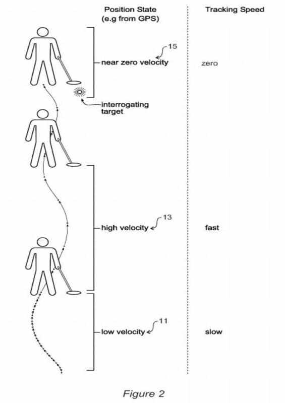
Coil position awareness acquired from GPS/Accelerometer/Optical sensors allow for variable ground tracking speeds based on coil speed and position. Helps reduce ground noise and EMI.
Here is a brief list of possible benefits of the new technology
- Automatic/variable ground balance adjustment based on swing speed
- Mitigation of electromagnetic inference [EMI] 😀😀😀😀
- Contour Map shown on a visual display
- Increased confidence level on targets in the ground
- Priority based targeting
- Mineralisation mapping (e.g. soil magnetic response, soil phase (or ground balance adjustment required))
- Ground based imaging SLAM using optical sensor [Mobile phone camera?]
- Augmented reality for detector training
- Priority target based acquisition
The detector would incorporate a visual display with a touch screen. This enables the user to see a target overlay and to touch the screen to bring up further information about that target. Alternatively, when there is useful information available, a small icon ℹ️ pops up without displaying the information ensuring the display is not cluttered. Touching the icon allows information in relation to the target to be displayed. For example, at a location, there is information in relation to a non-ferrous coin, a small
“coin” icon pops up on screen. When the icon is touched/pressed by the user, information such as the depth is displayed.
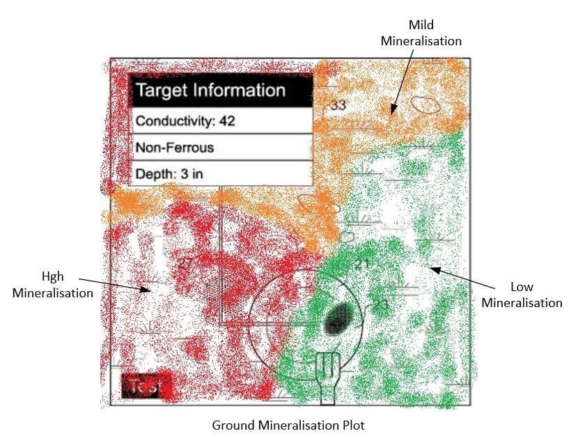
Figure [7] Representation of visual display showing target information including conductivity / non-ferrous and depth. Indication of ferrous target shown shaded [27], non-ferrous target [23] under the coil. Priorities could be set so that non-ferrous targets get preference over ferrous [nail] thus assisting when detecting in an area with a large number of targets.

To improve the accuracy of the location of the detector coil, apart from the less accurate GPS system, a technology called SLAM [Simultaneous Localisation and Mapping] could be employed by the optical sensor in the detector. This is basically an imaging technique used to construct a map of an unknown environment, or in this case with the assistance of GPS a known environment with higher local accuracy. Combining all data including target identification could then be presented on the detectors visual display.
Mineralisaion mapping could be extremely valuable for all Gold prospectors obtained from the soil magnetic response and soil phase. This could then be represented on the color detector display. A visual representation is shown below.
In conclusion it seems that the patent lodged and the technologies discussed and the fact that the patent is named GEO SENSE-PI, leads me to believe that the new model when released will indeed be a high end PI Gold/Relic detector. I also believe that Minelab having US$30million+ to invest into R&D will actually make this happen. Exciting times ahead, start saving those pennies.
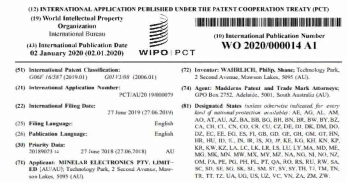
All information in this article has been obtained from the International Patent shown below.
I hope you enjoyed this article and ask that you comment below.


